
The dual-active data center solution refers to the situation where both data centers are in operation and can simultaneously handle production business, thereby enhancing the overall service capability and system resource utilization of the data center, achieving the strict requirements of RPO (Recovery Point Objective) and RTO (Recovery Time Objective), and elevating the continuity of enterprise business systems to a higher level. Currently, the most core technology in the end-to-end dual-active data center solution is the storage dual-active technology, which is also one of the dual-active technologies that enterprises pay attention to. Among the existing content about storage dual-active, it is generally an overall overview of the storage dual-active solution, starting from the products provided by the manufacturers to organize the solution content. It is difficult to provide favorable support for the actual implementation of the enterprise's storage dual-active project, thus making the project implementation prone to being bound by the manufacturers. Therefore, in this content of the storage dual-active solution analysis, the author will objectively and comprehensively analyze and compare the mainstream storage dual-active solutions in the industry from multiple perspectives such as solution characteristics, third-site arbitration, two-location three-center expansion, read-write performance, fault transfer, and dual-active capabilities, involving storage dual-active solutions from five different storage manufacturers, such as Huawei, EMC, IBM, HDS, and NETAPP, to help enterprises truly solve the implementation difficulties of storage dual-active construction. This article will analyze the solution characteristics of the five mainstream storage dual-active solutions.
A. Huawei HyperMetro
1. Overview of Dual-Active Solution
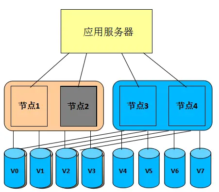
The dual-active solution for Huawei's storage layer is implemented based on the HyperMetro feature of the OceanStor integrated storage system. HyperMetro adopts an AA dual-active architecture to combine two storage arrays into a cross-site cluster, enabling real-time data mirroring. The dual-active LUN data on both arrays is synchronized in real time, and both arrays can simultaneously handle the I/O read and write requests of application servers, providing application servers with parallel access capabilities without any interruption of business access in case of any failure of a disk array. When any disk array fails, the business automatically seamlessly switches to the opposite end storage for access, without any interruption of business.
2. Key Features of the Plan
(1) Gateway-free Design: The Hyper Metro dual-active architecture does not require the deployment of additional virtualization gateway devices. It directly uses two sets of storage arrays to form a cross-site cluster system. It supports up to 32 storage controllers, meaning that two sets of 16-controller storage arrays can establish a dual-active relationship.
(2) I/O access path: On the application host side, Hyper Metro uses UltraPath host multipath software to aggregate the dual-active member LUNs on the two storage arrays into a dual-active LUN. It provides I/O read and write capabilities to the application in the form of multi-path Vdisk. When the application accesses the Vdisk, UltraPath selects the optimal access path based on the multi-path mode and then issues the I/O request to the storage array.
Based on the deployment distance of the dual-active sites, Hyper Metro provides two I/O access strategies for selection. One is the load balancing mode: In this mode, I/O can be load balanced across the arrays, that is, I/O is dispatched in a fragmented manner to both arrays. The size of the fragments can be configured. For example, if the fragment size is 128M, then I/O starting from 0-128M is dispatched to Array A, 128M-256M to Array B, and so on. The load balancing mode is mainly applied to scenarios where dual-active services are deployed in the same data center. In this scenario, the performance of host business accessing both sets of dual-active storage devices is almost the same. To maximize the utilization of the resources of the two sets of storage devices, the host I/O is dispatched in a fragmented manner to both arrays.
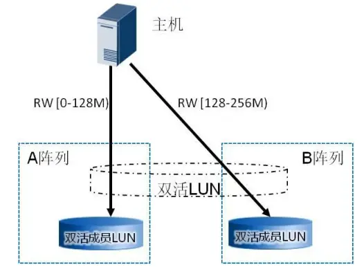
Another option is the preferred array mode: In this mode, the user specifies the preferred access array on OceanStor UltraPath. When the host performs business operations, I/O will be load-balanced and distributed only on the paths of the user-specified preferred array, without generating I/O accesses across arrays. Only when the preferred array fails will the I/O be switched to the non-preferred array. The preferred array mode is mainly applied in scenarios where dual-active business is deployed in two distant dual data centers. In this scenario, the cost of cross-site access is relatively high. If the link distance between the two data centers is 100km, a round-trip transmission usually takes about 1.3ms. The preferred array mode can reduce the number of cross-site interactions, thereby improving I/O performance. For the data read scenario, the business host of the dual-active data center only needs to read the dual-active storage array corresponding to its own data center, avoiding the host reading data across data centers and improving the overall access performance. For the data write scenario, the business host directly writes to the dual-active storage array corresponding to its own data center, avoiding the host forwarding data across data centers, fully utilizing the HyperMetro AA dual-active capability. Each controller of the AA cluster can receive write I/O, and the local controller processes the write I/O requests of the local host, reducing the number of cross-data center forwarding times and improving the overall performance of the solution.
(3) Storage Layer Networking: The following figure illustrates the typical networking architecture of the Hyper Metro dual-active solution. Three types of networks can be set up, including array and host, dual-active mirroring, and inter-city interconnection. The data network and the business network are separated; communication between the two dual-active storage arrays supports FC or IP links. FC links are recommended, but the RTT (round-trip time) between the sites must be less than 2ms. Additionally, the link between the storage array and the arbitration server uses a common IP link.

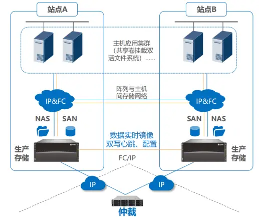
(4) Integrated Dual-Active: Under this scheme, a set of dual-active equipment supports both file data services (File Service) and block data services (Block Service), and can provide dual-active functionality in two ways: NFS file system and SAN block storage. SAN and NAS share one arbitration mechanism, which ensures that when the link between the two sites fails, file storage and block storage are provided by the same site, ensuring arbitration consistency. SAN and NAS share one network, and the heartbeat, configuration, and physical data links between the sites are unified. One network can meet the transmission requirements of SAN and NAS, and supports full IP deployment for business network, site-to-site network, and arbitration network. The networking is simple.


(5) Data consistency at the storage layer: Through dual write of I/O operations to ensure data consistency. Under normal system conditions, any IO data issued by an application must be simultaneously written to both arrays before being returned to the host, ensuring real-time consistency of data on both arrays. It also has a distributed lock mechanism (DLM) to ensure data consistency when the host accesses data at the same storage address. In the case of a single storage being unavailable, it has a data difference handling mechanism. When one storage is unavailable, only the normal storage is written to, while data changes are recorded in the DCL (Data Change Log) space. Once the array is repaired, HyperMetro will automatically restore the dual-active Pair relationship and write the data incrementally to the repaired storage based on the information recorded in the DCL. The advantage of this is that there is no need for full synchronization of all data. The entire process is transparent to the host and will not affect the host's business.

(6) FastWrite Technology: In the traditional general solution, the write I/O between two sites needs to go through two interactions of "write command" and "write data" during the transmission process. Theoretically, when the distance between the two sites is 100 kilometers, it will bring 2 RTTs (round-trip delays). See the left figure below; to improve the dual-write performance, the FastWrite technology combines "write command" and "write data" into one transmission, reducing the number of cross-site write IO interactions by half. Theoretically, for a 100-kilometer transmission link, it only requires 1 RTT, improving the overall write IO performance, see the right figure below.

(7) Cross-site bad block repair technology: To enhance data reliability, Hyper Metro has a cross-site automatic bad block repair function. It can automatically complete the repair process without human intervention, and the business access is not affected. The process is as follows (see the figure below): The production host reads data from storage A - > Storage A detects bad blocks through verification - > Attempts to repair the bad blocks through reconstruction, but the repair fails (if the repair is successful, the following process will not be carried out) - > Storage A checks and confirms that the status of the remote end "is complete" and simultaneously reads data from the remote end B array - > The data reading is successful, and the correct data is returned to the production host - > Use the remote data to repair the corresponding data of the local bad block.

(8) RAID 2.0 Technology: The storage array is capable of supporting multiple RAID protection technologies and further optimizing and upgrading on this basis. When any hard drive in the RAID group fails, through RAID 2.0 technology, the RAID can be quickly reconstructed and the data can be restored to the hot spare disk. The speed is significantly improved compared to traditional technologies, reducing the probability of multiple disk failures.
B.EMC Vplex
1. Overview of Dual-Active Solution
The EMC Vplex storage dual-active solution is implemented based on the Vplex gateway product. It can integrate heterogeneous EMC and other manufacturers' storage devices, virtualize them into a unified storage resource pool, and achieve dual-active for heterogeneous storage. The Vplex dual-active solution includes two schemes: Vplex Metro and Vplex Geo. The solution consists of two sets of Vplex cluster systems at each site. Each Vplex cluster system has its own dedicated local storage array. By creating distributed mirror volumes as cross-cluster mirror volumes, the Vplex Access Anywhere function is provided. Each Vplex cluster at the two sites has one volume, and the IDs of the two volumes are the same.
2. Key Features of the Plan
(Cluster Configuration: As shown in the figure below, each Vplex cluster consists of the Vplex Management Console, one, two, four or eight engines, and each engine includes a backup power supply. Vplex Local is used to manage data movement and access within the data center using a single Vplex cluster. It supports single, dual or four configurations (each containing one, two or four engines), and the local Vplex forms a Local cluster (with 4 engines and 8 controllers), and the two-site Local clusters then form a Metro/Geo remote cluster (up to 8 engines and 16 controllers), forming an AA cluster with 16 control nodes.)

(2) Synchronous/Asynchronous Solution: As shown in the figure below, Vplex Metro uses two Vplex clusters with unique functions. By adopting the write-through caching (transparent write) method, it mirrors data in real time between the two clusters to maintain the consistency of the backend storage data. Due to the real-time synchronous replication, the Vplex Metro solution must meet the requirement that the RTT (round-trip delay) between the sites is less than 5ms. Vplex Geo is used for the asynchronous use of Access Anywhere to access storage data by two remote application cluster nodes. The Vplex Geo distributed volume uses the write-back caching method to support the distributed mirroring of Access Anywhere. This solution can support the maximum RTT (round-trip delay) between sites of 50ms. Additionally, the clusters deployed under the Vplex Metro and Vplex Geo solutions do not require the number of engines between the sites to be exactly the same.

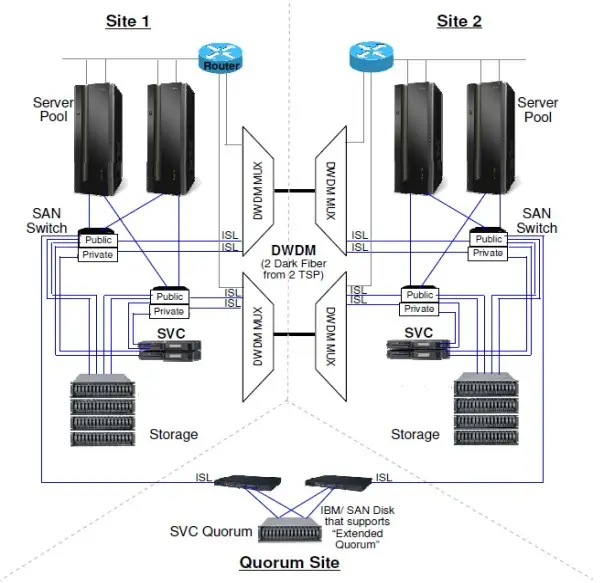
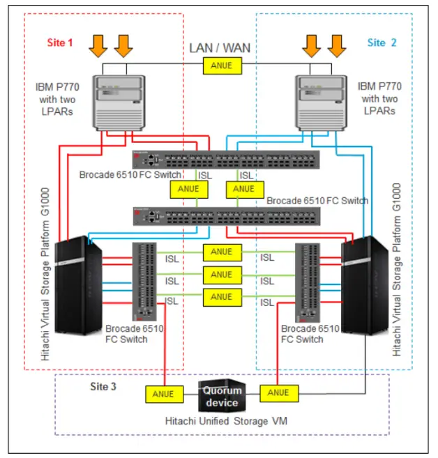
(3) Storage layer networking: The following figure shows the networking architecture for the cross-cluster connection of the host in the Vplex Metro dual-active solution. The access between the host and the Vplex cluster, the data transmission between the Vplex cluster and the backend storage, and the communication network between the Vplex clusters are all isolated. To ensure the highest level of high availability, there must be at least two physical connections between each Vplex Director front-end I/O module and a pair of SAN fiber switches. Each host and each Vplex engine's A Director and B Director need to maintain more than one path connection. Therefore, there are 8 logical paths between the host and one Vplex engine. For each Vplex cluster with 2 or 4 engines at a site, the host connection needs to cover all engines. Additionally, when the host connection to the local Vplex cluster is interrupted, to ensure that the host can access the other Vplex cluster across sites, the host needs to establish connections with other sites' Vplex clusters. This can be achieved by configuring the ACTIVE/PASSIVE paths through the PowerPath multiplexing software to ensure that the host prioritizes accessing the local Vplex cluster. The backend storage array is connected through a SAN switch or directly to the backend IO module of the Vplex engine, and does not require cross-site connection paths to other Vplex clusters. Based on the need, Witness can be used as an arbitrator. Witness needs to be deployed in different fault domains of the two Vplex clusters (third-party sites) and can only be deployed in the virtualized environment of VMware. It is connected to the two Vplex clusters via IP.

(4) Distributed Consistency Cache Technology: EMC Vplex is a cluster system that provides distributed cache consistency guarantees. It enables the unified management of the caches of two or more Vplex systems, allowing hosts to access a unified cache system. When a host writes I/O to a cache area of one Vplex, the Vplex cache will lock this cache area, and at the same time, other hosts cannot write I/O to this cache area. However, when a host reads I/O, the Vplex cache allows multiple hosts to access one cache area, especially when hosts access data managed by other Vplex nodes in other Vplex clusters, the unified cache management will inform the host of the specific cache location of this I/O, and the host can directly access across the Vplex cluster. In the implementation of this technology, it does not strictly require all caches to be unified, but tracks small memory blocks in the form of volume cache directories and ensures data consistency through the granularity of locks. Each engine's cache is divided into local Cache (Cache Local) and global Cache (Cache Global), and each engine's local Cache has only 26GB, and the rest is global Cache. See the figure below.
(5) Distributed caching mode: Vplex Local and Vplex Metro adopt the write-through caching mode. When the virtual volume of the Vplex cluster receives a write request from the host, the write I/O is directly written to the backend storage LUN mapped by this volume (Vplex Metro includes two sets of backend storage LUNs). After the backend array confirms the completion of the write I/O, Vplex will return a confirmation signal to the host, completing this write I/O cycle. The write-through caching mode requires waiting for the disk writing of the backend storage array to be completed, which has a high requirement for write I/O latency. This write-through caching mode is not suitable for the Vplex Geo solution. This solution can support a maximum cross-site round-trip delay of 50ms. Using this caching mode will have a very significant impact on the performance of the host, and for most applications, it is obviously unacceptable. Therefore, Vplex Geo adopts the write-back caching mode. In this mode, after Vplex receives the write request from the host, it directly writes to the cache of the engine controller and mirrors the write I/O to the memory of another controller of the engine and another Vplex cluster's engine controller. Then it confirms the current write I/O cycle to the host. Finally, the data is asynchronously transferred to the backend storage array of the engine. When a power failure occurs, the backup power of the Vplex engine can ensure that all un-persisted data in the cache is temporarily stored on the local SSD storage. The write-back caching mode does not need to wait for the disk writing of the backend storage array to complete, and can respond to the host immediately, significantly improving the distance and latency requirements of the Vplex failover solution.
(6) Read I/O acceleration capability: The mechanism of reading Cache and writing I/O can accelerate the read I/O process. To improve the performance of read I/O, before writing I/O, it first checks whether there is corresponding old data in the Local or Global Cache. If not, it directly writes to the Local Cache; if there is old data, it first invalidates the old data before writing it to the Local Cache; then, it flushes the write I/O to the two back-end storage arrays through the write-through cache mode (see the figure below); finally, it notifies the host that the write I/O cycle is completed, and simultaneously modifies the index in the Global Cache accordingly, and shares this information on all engines to achieve distributed cache consistency. Additionally, in this mechanism of Vplex, the write I/O requires an additional 2 cross-site round-trip delays (officially claimed to introduce a delay of 1-1.6ms), and in the Vplex Metro scheme, on the basis of the write-through cache, it sacrifices a certain write I/O performance.
When reading I/O, first read the Local Cache. If it is a hit, directly read it. The acceleration effect of this method is obvious. If it is a hit in the Global Cache, then read it from the corresponding Vplex engine Cache into the Local Cache, and then feed back the I/O reading result to the host. The acceleration effect is second. If it is not hit in the Global Cache, then read it from the local backend storage array into the Local Cache, and simultaneously modify the information and index information in the Local and Global Caches. The acceleration effect of this method has no effect.

(7) Support CDP technology: Vplex only provides two functions of storage heterogeneous virtualization and mirroring. Snapshots, replication and other features need to be implemented using EMC's own RecoverPoint. Therefore, the networking method of Vplex often considers using it in conjunction with RecoverPoint. In addition, Vplex integrates I/O diversion software internally. Vplex synchronously replicates each host write I/O to RecoverPoint, and RecoverPoint records each I/O. CDP is used to achieve recovery at any point in time. The following figure shows a comparison of the write I/O process between the Vplex dual-active and the Vplex dual-active + RecoverPoint CDP solution. The latter will increase write I/O latency and I/O amplification, affecting certain performance.


C.IBM SVC
1. Overview of Dual-Active Solution
IBM has provided two different solutions for SVC storage dual-active technology: Enhanced Stretch Cluster and HyperSwap. Both are active-active data center storage dual-active solutions based on virtualized storage platforms, providing storage A-A dual-active or high availability architectures for upper-layer applications, ensuring that any component failure in the storage layer will not affect the upper-layer applications. SVC Enhanced Stretch Cluster, also known as SVC Stretch Cluster Architecture, is to stretch the dual nodes in the same SVC I/O Group that operate in protection mode across different sites, distributing them in two different data centers. They are connected through fiber links, and data is mirrored in real time to two storage devices on each site using Vdisk Mirror technology. SVC HyperSwap, compared to SVC ESC, mainly aims to eliminate the single-point隐患of local SVC nodes, increase the redundant storage paths for hosts, and further enhance the high availability of SVC dual-active. Through Metro Mirror technology, data is synchronized in real time between the two I/O Groups and the two sets of storage, and at the same time, it solves the performance problems caused by the failure of a single SVC node and the problem of data volume being inaccessible due to the failure of both nodes. Both of these two solution architectures are symmetrical architectures, and arbitration can be configured at the third site to prevent the occurrence of brain split phenomenon.
2. Key Features of the Plan
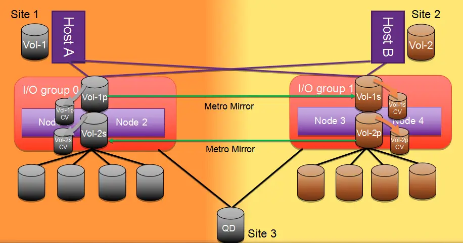
(1) Overall Architecture: The SVC ESC adopts the Stretched topology architecture (as shown in Figure 1), with at least one node at each site, and each site has one set of storage. Through SVC VDM, real-time synchronization is maintained. For the host, only one Vdisk is seen. The host establishes connection paths with the SVC nodes at both sites to enable each site's host to read and write the local SVC node and storage independently, achieving the goal of Active-Active storage. The storage networks of the two sites are cascaded through bare optical fibers between DWDMs; The SVC HyperSwap adopts the HyperSwap topology architecture (as shown in Figure 2), with at least one I/O Group at each site, and each I/O Group is configured with two SVC nodes, enhancing the redundancy of the local SVC nodes. Each site has one set of storage, and through SVC Metrol Mirror, real-time synchronization is maintained. For hosts of different sites, different LUNs are seen. The host establishes connection paths with the two I/O Groups across sites, improving the redundancy of the paths.
(2) Fiber optic link networking and arbitration: Both schemes can achieve access isolation by establishing two types of FC networks, namely Private and Public. The Private network is used for data synchronization and heartbeat between two SVC nodes or between two groups of SVC I/O Group Caches. The Public network is used for data transmission between the host and the SVC node, or between the SVC node and the storage. The FC storage networks of the two sites are cascaded through two pairs of cross-site DWDM (Wavelength Division Multiplexing) fibers. In terms of arbitration methods, two modes are supported: the arbitration disk mode and the arbitration server mode. The arbitration disk mode uses FC links, while the arbitration server mode uses IP links.


(3) I/O Access Path: Under the SVC ESC scheme, the host needs to configure I/O paths to the SVC nodes at this site and the remote site to ensure that in case of a failure at the local site node, the host path can immediately switch to the remote site for accessing other SVC nodes under the same I/O Group. In the SVC HyperSwap scheme, the cross-site host access node path is an optional configuration. To avoid a long RTO in the scenario where all storage paths at the site fail (APD), it is recommended to configure the cross-site host access node path. At the host end, through the SDDPCM multipath software and by configuring the path policy based on ALUA, it is specified which SVC node is the local node of the host to prevent the host from accessing other SVC nodes across sites. When the local paths are not all failed, the host will preferentially access the Preferred Node of the SVC HyperSwap I/O Group at this site. When the local paths are all failed, the host will cross-site access the SVC HyperSwap I/O Group at the remote site, but the ALUA policy cannot identify which one is the SVC Preferred Node at the remote site. Therefore, the ALUA policy will change to Round-Robin, polling the ports of all SVC nodes at the remote site.
(4) SVC ESC Site Awareness Function: All objects at both sites possess site-specific attributes, including SVC nodes, hosts, storage, etc. This reduces the concept of I/O Group Preferred Node in the SVC Local cluster. In the I/O Group, both nodes are equal. The hosts at the two sites can access the same Vdisk through the parallel access of two SVC nodes in the same I/O Group. That is, local read I/O optimization, local write I/O optimization, ensuring I/O localization, and avoiding the performance impact caused by remote I/O access.


(5) Characteristics of SVC ESC caching mechanism: Each node of SVC contains several capacities of cache, which are used to temporarily store host I/O data, thereby reducing the performance impact caused by physical disk writing of I/O. SVC is placed between the host and the storage, and does not increase the I/O latency of the host accessing the storage. SVC has the effect of expanding the cache of low-end storage and to some extent enhances the performance of low-end storage; If a certain node of the I/O Group of SVC ESC fails, another node takes over, the write cache is disabled, and it enters the write-through mode, with a slight performance decrease (compared to SVC HyperSwap in the scenario of site failure, the remote I/O Group still has a complete write cache protection mechanism, which can avoid the performance decrease caused by directly entering the write-through mode); One I/O Group of SVC ESC adopts a set of cache tables, so it can achieve the lock mutual exclusion mechanism for write I/O, realizing the true dual-active of two SVC nodes and the storage of the same Vdisk, and having host read-write affinity; When the power supply of any SVC node fails, the built-in battery or the external UPS module of SVC can continue to supply power until all the cache data in the SVC node is flushed into the back-end storage array, and then the SVC node is turned off.
(6) SVC HyperSwap Master-Slave Volume Mechanism: After establishing the relationship of the HyperSwap volumes, the hosts at the two sites respectively map the Master volume and the Aux volume, indicating which volume is serving as the master volume and providing all I/O services. The SVC I/O Group with the Master volume, all read and write requests from both sites must pass through this I/O Group. If the I/O Group of the Master volume and the host are in the same site, the host at this site can locally read and write the I/O Group and the back-end storage array. If the I/O Group of the Master volume and the host are not in the same site, the host at this site forwards the request to the I/O Group of the Master volume for processing the read and write requests. HyperSwap will automatically compare the local I/O traffic and the I/O traffic for forwarding, to determine whether to reverse the attributes of Master and Aux. I/O traffic refers to the number of sectors rather than the number of I/O operations. After the first creation of the HyperSwap volume and initialization, the system automatically determines which volume is the Master. If the I/O traffic (read-write forwarding I/O traffic) of the Aux volume exceeds 75% of all I/O traffic for more than 10 consecutive minutes, the attributes of the Master and Aux volumes will be reversed. This method can avoid frequent reversals. Based on these characteristics, under the HyperSwap master-slave volume mechanism, the hosts at the two sites can achieve local I/O Group local reading and writing, but the two sets of cross-site storage are in the ACTIVE-STANDBY mode. The back-end storage array mapped by the Master volume is the primary storage, and the back-end storage array mapped by the Aux volume is the hot standby storage.
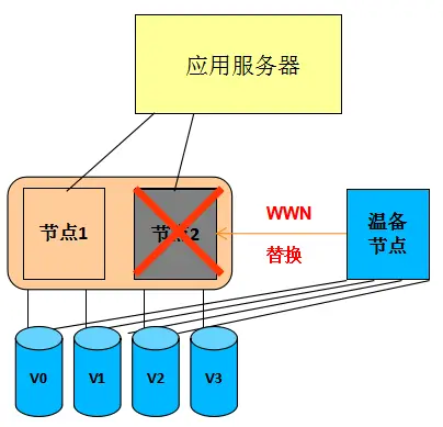
(7) SVC Seamless Volume Migration Technology (NDVM): This technology enables the migration of virtual volumes to different I/O Groups, enabling rapid response to node failures and conducting batch automated migrations of virtual volumes that are prone to single-point failures. It also enables the batch automatic migration of different I/O Groups, eliminating the isolation of individual I/O Groups within the cluster and forming redundant protection among multiple I/O Groups (as shown in the leftmost and second-leftmost figures below). This technology is implemented through a lightweight application built into SVC, which is simple to deploy, easy to use, and has low system overhead. Additionally, it can quickly restore the cluster to its normal state by rapidly replacing the failed node with a warm standby node (as shown in the rightmost figure below).


D.HDS GAD
1. Overview of Dual-Active Solution
The Global-Active Device solution of the HDS VSP series storage uses a unique Hitachi Storage Virtualization Operating System (SVOS) to implement it. This solution is supported in both the G series (G1500, G1000, G800, G600, G400, G200) and the F series (F1500, F800, F600, F400) storage systems, enabling global storage virtualization, distributed continuous storage, zero recovery time and zero recovery goals, simplified distributed system design and operation. Global storage virtualization provides "global active volumes". These storage volumes can simultaneously read and write two copies of the same data in two storage or sites. This Active-Active storage design allows two storage systems to run production workloads simultaneously in a Local or metro cluster configuration, while maintaining complete data consistency and protection.
2. Key Features of the Plan
(I/O Access Path): As shown in the figure below, GAD adopts an Active-Active architecture and supports simultaneous reading and writing by the primary and secondary arrays. All I/O write operations are performed by first writing to the primary LUN and then to the secondary LUN. The preferred path is configured through the original factory HDLM multipath software, which can support the local priority read/write strategy. Versions after G1000 support the ALUA function, which automatically identifies the preferred path for the local site and is also compatible with third-party multipath for mainstream OS. When all local paths fail (APD scenario), the host will continue to access the remote storage across sites through the StandBy path. Usually, the primary and secondary sites support a distance of 100KM, support FC/IP replication links, support 8 physical paths and cross-networking between the array host. In versions after VSP G1000, VSP G1500, and VSP F1500, the maximum support for SAN dual-active is 500KM (RTT round-trip delay 20ms); the maximum support for 32 arbitration disks (storage or server disks), and does not support the virtual machine or physical machine IP arbitration method.

(2) Storage layer networking: The networking of GAD is relatively flexible. The single-machine dual-array networking is used in data centers and can only achieve the dual-active capability of the storage layer. The server host is a single point, and it can only prevent storage failures. This networking method is commonly used in applications that do not support clustering; the dual-server dual-array networking is a relatively common networking method. This networking requires servers to install cluster software to achieve business switching. This networking can achieve business dual-active in both the storage layer and the application layer; cross-networking is similar to the dual-server dual-array networking method, but it realizes cross-redundancy at the network layer. This is the recommended networking method, that is, servers can all see all the storage, and servers simultaneously use cluster software and multipath software to complete fault switching. The switching method is more reasonable. For example, in the case of storage failure, the server cluster does not need to switch, only the multipath software needs to switch the storage. The following figure is the local simulation cross-site GAD networking topology diagram. The host accesses the storage network, the inter-site mirroring return network, the cross-site storage access network between the hosts, and the third-site arbitration network are all isolated. The host of Site 1 writes to the VSP storage of Site 1 through the red path, and synchronizes the mirrored data to the VSP storage of Site 2 through the inter-site ISL network. The host of Site 2 writes to the VSP storage of Site 2 through the blue path, and synchronizes the mirrored data to the VSP storage of Site 1 through another pair of ISL networks between the sites.


(3) Virtual Storage Machine (VSM): HDS enables users to define multiple VSMs within a single physical storage based on business and application requirements. Each VSM is similar to a single storage unit and has its own storage ID, device serial number, and port WWN. Through the definition of VSMs, storage resource utilization can be effectively improved, and maximum flexibility in architecture and business can be achieved. The VSP can support up to 8 VSMs, but it can also support 63,231 pairs of dual-active GAD volumes. HDS GAD technology uses the method of setting SVM to make two storage units use the same virtual serial number, allowing the host to view two physical storage units (which may contain multiple SVMs) as one storage unit. Within a single physical storage, users can define multiple VSMs based on business and application requirements. VDC is a virtual controller created on the VSP. It can virtualize multiple storage underlying physical controllers into a single controller, so when the host accesses the back-end disk resources through the virtual controller, it always interacts with a controller ID, regardless of how the background storage changes, and thus achieves features such as dual-active.
(4) Microcode for Data Consistency: HDS GAD achieves dual-active through microcode. The host, switch, and storage in the entire I/O path do not require any additional devices. The HDS GAD technology does not add any unnecessary steps during the host write I/O process. The implementation method is the enhanced synchronous replication technology TrueCopy. Both sides complete the write I/O process before returning it to the host. The entire process ensures data integrity. When two hosts write the same storage block simultaneously, HDS will lock the write storage block to ensure data consistency. The host read I/O maintains site affinity through multiple paths and reads from the local location.
(5) HDS 3DC Technology: HDS supports the "active-active + replication" 3DC mode, namely HDS GAD + asynchronous storage replication, and also supports 3DC triangular incremental replication for SAN and NAS. The asynchronous replication between the primary site and the remote site records data differences through logs. Both the active-active primary and secondary LUNs record the differences from the disaster recovery site. The difference records start by aligning the log IDs. When a dual-active node fails, the other node continues to replicate with the remote disaster recovery site, and the differential data can be obtained by querying the log IDs.

(6) Hardware implementation supports snapshots and cloning: The snapshot and cloning functions of HDS are implemented based on dedicated hardware, featuring high performance and the snapshots are accessible to both the master and slave nodes.
(7) HNAS + GAD dual-active: HDS achieves NAS dual-active through the HNAS gateway in conjunction with VSP GAD. Refer to the following figure. It provides SAN block storage services and NAS file system services externally. However, NAS dual-active relies on SAN dual-active. Currently, HNAS supports binding 2 HNAS gateway clusters with GAD to form a remote Active-Passive dual-active configuration. Data reading and writing are completed at the primary end, but at the secondary end, through configuration of Cache and CNS, partial reading can be supported. The entire HNAS file system data is saved on the GAD dual-active device. The main task of the HNAS node is to synchronize metadata, status, and control data between sites.

(8) HNAS + GAD dual-active network configuration: As shown in the figure below, the NAS cluster's NVRAM data replication supports a 100KM 10GE network configuration. The GAD master-slave sites claim to support a 500km FC network configuration, and can support up to 8 physical links. HNAS nodes and GAD support cross-networking, and in the APD scenario, only the I/O paths are switched, without switching the HNAS gateway; NAS adopts an arbitration server mode, supporting GE network configuration, while SAN adopts an arbitration disk mode for arbitration, with the connection between the master-slave sites and the arbitration using FC links. SAN and NAS use two independent arbitration systems. In terms of network complexity, HNAS requires an independent arbitration network, management network, mirror network and NAS service access network, and GAD also requires an independent arbitration network, management network, data mirror network and SAN storage service access network, totaling 8 types of networks. There is a large demand for network interfaces and the architecture and configuration are relatively complex.

E.NetApp MetroCluster
1. Overview of Dual-Active Solution
Clustered Metro Cluster (abbreviated as MCC) is a storage failover solution provided by Netapp Data Ontap. It can enhance the built-in high availability and uninterrupted operation functions of NetApp hardware and ONTAP storage software, providing an additional layer of protection for the entire storage and host environment. By combining two controllers of a FAS/V series storage and using fiber optic or fiber optic switch to increase the distance between the controllers, an异地 HA Pair is formed. The controllers achieve Aggr-level data mirroring through SyncMirror, and the storage mirroring is physically separated. To further enhance the redundancy of the local controller, two controllers are placed in both the local and remote locations. The two controllers in the local area form a pair of HA Pair, and the two pairs of clusters in the local and remote locations form a four-node cluster, providing mutual protection.
2. Key Features of the Plan
(1) Storage layer networking: The networking of the Metro Cluster storage layer is very complex. The primary and secondary sites support 300 kilometers of FC networking; SAN Cluster can support up to 12 controllers, and NAS Cluster can support up to 8 controllers. In the networking of the 4 control nodes in the following figure, three types of network interconnection devices, six types of network types, and 12 sets of network equipment need to be configured simultaneously: including 4 sets of FC-to-SAS conversion devices, 4 sets of FC switches, and 4 sets of 10GE switches. The dual control within the engine does not support PCI-E interconnection and needs to be interconnected through an external 10GE/4GE Ethernet network; the arbitration of the third site can choose an IP link, and the TieBreaker arbitration software can be directly installed on the Linux host.

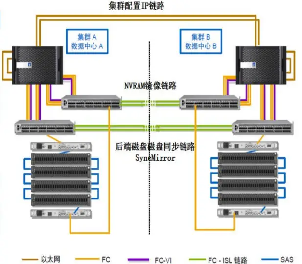
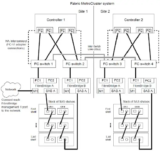

The Metro Cluster involves several types of data synchronization, including configuration synchronization between the two clusters, log synchronization of NVRAM, and backend disk synchronization. In the system, these three types of data synchronization use different networks. The network for the two cluster configuration synchronization: Through a dedicated redundant TCP/IP network, the CRS (Configuration Replication Service) service synchronizes the configuration data of the two clusters in real time, ensuring that configuration modifications at one end of the cluster, such as adding an IP, SVM, or adding, deleting user shares, can be automatically synchronized to the remote HA Pair cluster; the network for NVRAM log synchronization: Uses an additional redundant FC-VI cluster adapter to connect the two cross-site controllers. FC-VI supports RDMA and QoS functions, used for NVRAM synchronization and heartbeat between the two clusters, which can ensure the priority of the heartbeat while reducing the number of data write I/O transmissions, because RDMA supports the technology of batch acquisition of a group of address spaces, after batch acquisition of a group of addresses, the data is directly transmitted, optimizing the two-time write of the FC protocol into one; the dual write network for backend data offline: The controller and the storage array use a unique FC-to-SAS device. The controller data transmission uses the FC network, while the backend disk array needs to be connected through SAS for networking. Therefore, it is necessary to first perform FC and SAS conversion (Fibre Bridge), and connect the two site controllers and the backend disks with designated Cisco and Brocade model dedicated switches to complete the protocol conversion.
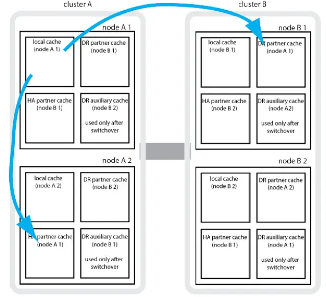
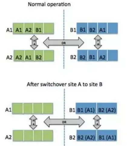
(2) Metro Cluster Cluster: Each controller of the Metro Cluster divides its NVRAM into 4 areas, which are respectively used for storing local node logs, HA Pair Partner logs, remote HA Pair Partner logs, and remote HA Pair auxiliary logs (for switchover). When a new write operation is initiated, it is first written to the local area, then synchronized to the local HA Pair's NVRAM and the remote DR Pair's NVRAM, and then a success message is returned; when the local controller fails, the service is prioritized to be switched to the HA Pair node; after the controller recovers, it automatically switches back; only when the entire site fails will the service be switched to the remote site for operation. The switchover time is controlled to be within 120 seconds and does not affect the upper-level services.


(3) SyncMirror Synchronization: SyncMirror is the core data synchronization technology of Netapp's dual-active solution. When writing to the NVRAM log, it enables dual writes of the disks at the primary and secondary sites. SyncMirror operates at the Aggregate layer, and the mirrored Aggregate consists of two Ples. The Plex0 from the local Pool0 and the Plex1 from the remote Pool1. Write process: When the NVRAM log starts to be written to the disk, the write request is simultaneously written to the local Plex0 and the remote Plex1. Both sides complete the write successfully before returning a success message. Read process: Data will be read from the local Plex0 first. The read permission of the remote Plex1 needs to be enabled through a command. By default, the remote Plex1 does not provide read services.

When there is a single-sided failure on the Plex site, incremental recovery is performed through the snapshot of the Aggregate. By default, space in the Aggregate is reserved to create snapshots for the Aggregate's snapshot, serving as the baseline data for the re-synchronization of the Aggregate. If no snapshot is made, a full synchronization is required for recovery after a Plex failure.
(4) AP Architecture: The NetApp MCC solution is based on a disk mirroring architecture. For the upper-level applications, they only see one LUN/file system. Through the mirroring Aggregate, dual-active is achieved. Under normal circumstances, reads are performed from the local Plex, and writes will synchronize the data to both the local and remote Plexes. Whether it is a 2-node or 4-node MetroCluster cluster, at any given moment, the LUN/file system can only be provided to one node that constitutes the cluster's HA Pair. Only when this node fails, the Partner node of the HA pair will take over the provision of services, or when the entire site fails, the HA pair cluster from the secondary site will take over the services. Site switching can be triggered manually by executing the CFOD command or through the TieBreak arbitration software automatically. Therefore, fundamentally speaking, it is dual-active for different engines of a set of arrays, not dual-active for the same LUN. Thus, it is merely array dual-active in the Active-Passive mode.
(5) Heterogeneous Virtualization: Capable of managing heterogeneous storage in the existing network, but does not support dual-active between local disks of the FAS series and heterogeneous storage. It supports dual-active between two sets of heterogeneous storage from the same manufacturer, of the same model, and with the same Firmware. When taking over heterogeneous storage, the original array data will be damaged. Before taking over, the original array data needs to be migrated to another location. After taking over, the original data will be migrated back.
(6) Rich value-added features: All FAS series products (FAS3240, FAS3210, and FAS3270, except FAS2xxx) support MetroCluster and do not require separate licenses. The product base package already includes this function. It can simultaneously support dual-active for both SAN and NAS, achieving integrated dual-active for block storage and file storage. Other value-added features include SSD acceleration, snapshots, replication, data compression, thin provisioning, deduplication, etc.
Bibliography:
华为业务连续性容灾解决方案双活数据中心解决方案技术白皮书
Clustered Metro Cluster双数据中心存储方案
HAM/GAD双活数据中心存储方案
Vplex双活数据中心存储方案